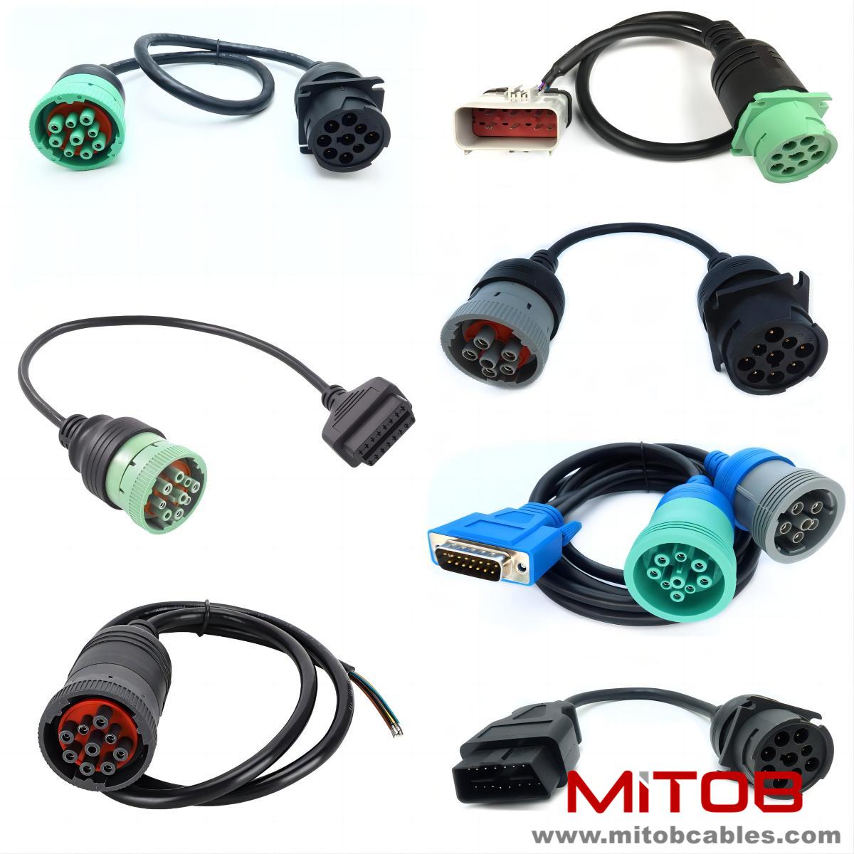
How to diagnose the fault of J1939 to J1708 cable
The fault of J1939 to J1708 cable can be diagnosed according to the following steps:
Appearance inspection:
Check the surface of the cable for any abnormal phenomena such as damage, aging, burn marks, oil leakage, etc. If there is damage, it may expose the internal core wire, causing a short circuit or grounding fault; Aging cables can lead to a decrease in insulation performance and are prone to issues such as electrical leakage.
Check if the cable joints are loose, oxidized, or corroded. Loose joints can cause an increase in contact resistance, leading to heating and unstable signal transmission; Oxidation and corrosion can affect the quality of signal transmission.
Inspect the cable path to see if there is any external damage, tree compression, or other conditions. External damage may directly damage the insulation layer and core wire of the cable, affecting signal transmission.

Preliminary judgment of fault type:
Observe the operating status of relevant equipment, such as whether there are abnormal phenomena such as voltage fluctuations, excessive current, and equipment errors. For example, if voltage instability occurs, it may be due to poor contact or insulation damage in the cable; If the current is too high, there may be a short circuit fault.
Check the relevant indicator lights, alarm information, etc. to obtain more clues about the fault. If the fault indicator light on the device lights up, the approximate direction of the fault can be preliminarily determined based on the corresponding manual or instruction manual.
Measure insulation resistance:
Measure the insulation resistance of the cable using a megohmmeter. Connect one end of the megohmmeter to the core wire of the cable and the other end to the outer sheath or grounding terminal of the cable, and measure the insulation resistance between the core wire and the outer sheath, as well as between different core wires.
If the insulation resistance is too low or fluctuates greatly, it indicates a decrease in insulation performance, and there may be grounding or short circuit faults. For J1939 to J1708 cables, it is generally required that the insulation resistance be within a certain range. Specific values can refer to relevant standards or equipment manuals.
Conductivity test:
Short circuit the three phases at the end of the cable and use a multimeter to measure the resistance between the core wires at the beginning of the cable. Under normal circumstances, the resistance value should be within a reasonable range. If the resistance value is too large or infinite, it indicates the presence of a wire breakage fault.
A cable continuity testing device can also be used to establish the connection between the input channel of the testing equipment and the starting end, as well as the connection between the output channel of the testing equipment and the ending end, based on the physical addresses corresponding to the starting and ending ends of the tested cable. Then, a point-to-point continuity test can be initiated from the starting end to the ending end, and the continuity resistance of the cable can be determined based on the test results to determine whether it is within the preset resistance criterion range, thereby identifying whether the cable is a faulty cable.
Using professional instruments for distance measurement:
Use a cable fault tester to measure fault distance. Modern traveling wave methods, such as low-voltage pulse method and high-voltage pulse method, are suitable for ranging various cable faults.
The low-voltage pulse method is to send a low-voltage pulse signal to the cable. When the signal encounters a fault point, it will generate a reflected wave. Based on the time difference between the transmitted wave and the reflected wave, as well as the propagation speed of the signal in the cable, the distance from the fault point to the measuring end is calculated. The high-voltage pulse method is suitable for high resistance faults and flashover faults. By applying high-voltage pulses to generate an arc at the fault point, the electromagnetic waves generated by the arc are used to determine the location of the fault point.
Fault location:
After ranging, the fault location is accurately determined near the fault point using techniques such as acoustic magnetic synchronization, electromagnetic predetermined point method, or audio fixed-point method based on the cable path direction.
The acoustic magnetic synchronization method utilizes the sound and electromagnetic wave signals generated during the discharge of a fault point, and receives these two signals through specialized instruments to determine the location of the fault point based on the time difference between them. The audio fixed-point method injects audio signals into the cable and uses an audio detector on the ground to detect the strength of the signal along the cable path. When the signal is strongest, it is the location of the fault point.
Error analysis:
After the testing is completed, conduct error analysis on the test results. Check if there are any issues such as improper operation or insufficient instrument accuracy during the testing process, summarize the gains and losses during the testing, in order to improve the efficiency and accuracy of future fault diagnosis.
For example, if there is interference in the testing environment, it may affect the accuracy of the test results; Or inaccurate calibration of the instrument can also lead to measurement errors. By analyzing and improving these factors, cable faults can be better diagnosed.
If there are still difficulties in diagnosing the J1939 to J1708 cable fault, it is recommended to consult a professional electrical engineer or relevant technical personnel for more accurate and effective diagnostic methods.
Contact: Kevin
Phone: 0086-18823374992
E-mail: kevin@mitobcable.com
Whatsapp:
Add: Bld B2, Floor7 , Xinghe Zhongkai AI Industrial Park, Zhongkai High-tech Zone, Huizhou,China