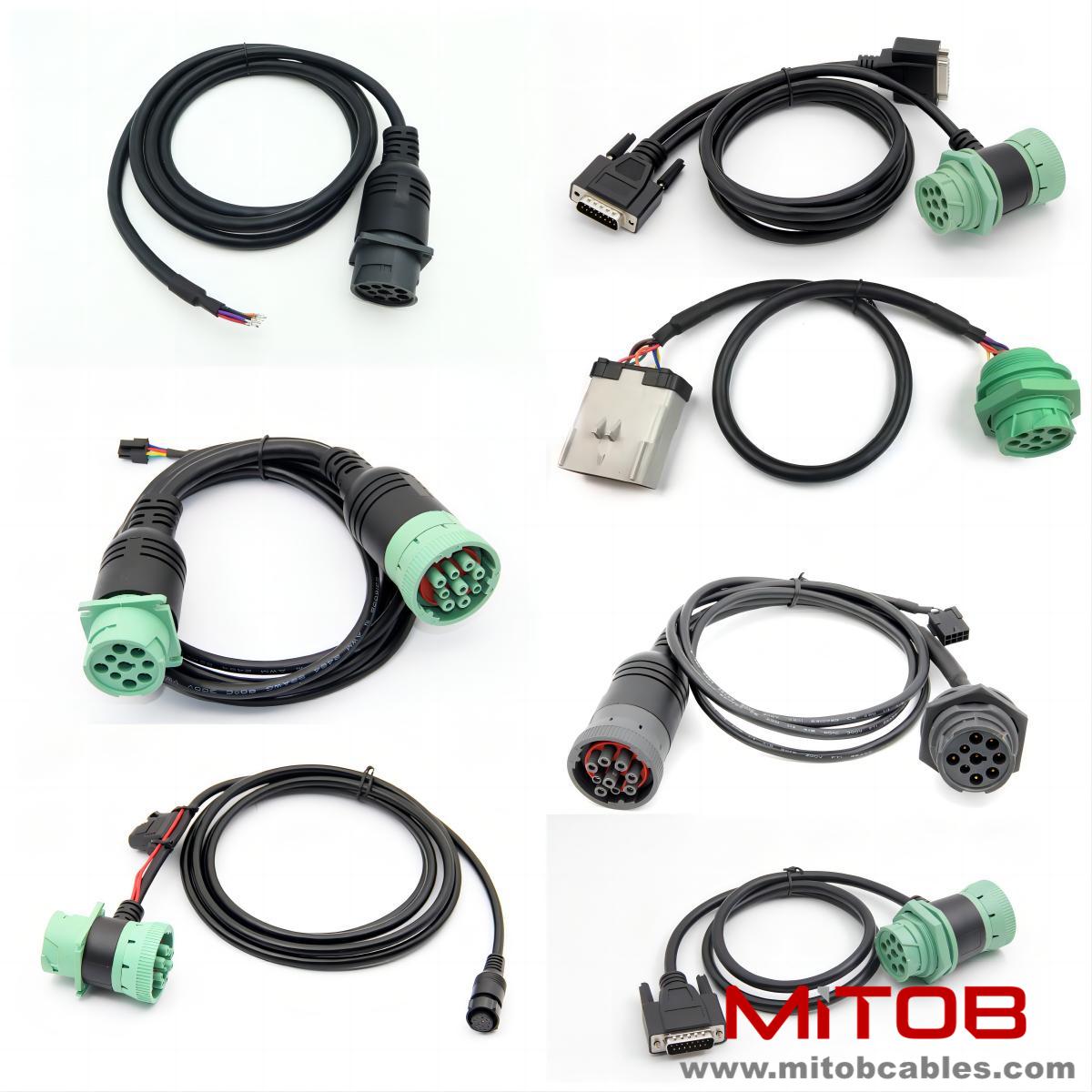
What are the configurations of J1939 cables?
Data link layer configuration
CAN protocol extension
29 bit identifier: J1939 is based on the CAN 2.0B extended frame format and supports more complex addressing and priority management.
Parameter Group Number (PGN): Used to distinguish different parameter groups (such as engine speed, vehicle speed, etc.) to ensure accurate data transmission.
Priority and scheduling mechanism
Priority range: The message priority ranges from 0 (highest, such as emergency braking signals) to 7 (lowest, such as non critical diagnostic data), with a total of 8 levels defined by the first 3 digits of the identifier.
Time slice polling scheduling: High priority messages are sent first, while low priority messages are processed later to avoid bus conflicts and ensure real-time performance.
Multi packet transmission support
Transmission Protocol (TP): Multiple packet data transmission is achieved through PGN 0x00EC00 (TP. CM) and 0x001B00 (TP. DT).
TP.CM: Manage connection establishment, traffic control, and packet sequence numbering.
TP.DT: Transmit actual data.

Diagnostic interface configuration
Standardized diagnostic connector
Diagnostic Message (DM): Covering Unified Diagnostic Communication Service (UDS) functionality.
Diagnostic Trouble Code (DTC): Includes Fault SPN (Suspected Parameter Number), FMI (Fault Mode Identifier), and occurrence counter, used to accurately locate faults.
Real time diagnosis and display
Independently sending diagnostic messages: ECU can actively send diagnostic information during normal operation without the need for external tools to trigger.
Tool reading error: Read DTC through diagnostic connector, supporting real-time monitoring and troubleshooting.
Contact: Kevin
Phone: 0086-18823374992
E-mail: kevin@mitobcable.com
Whatsapp:
Add: Bld B2, Floor7 , Xinghe Zhongkai AI Industrial Park, Zhongkai High-tech Zone, Huizhou,China